

Peltier Bottle Warmer
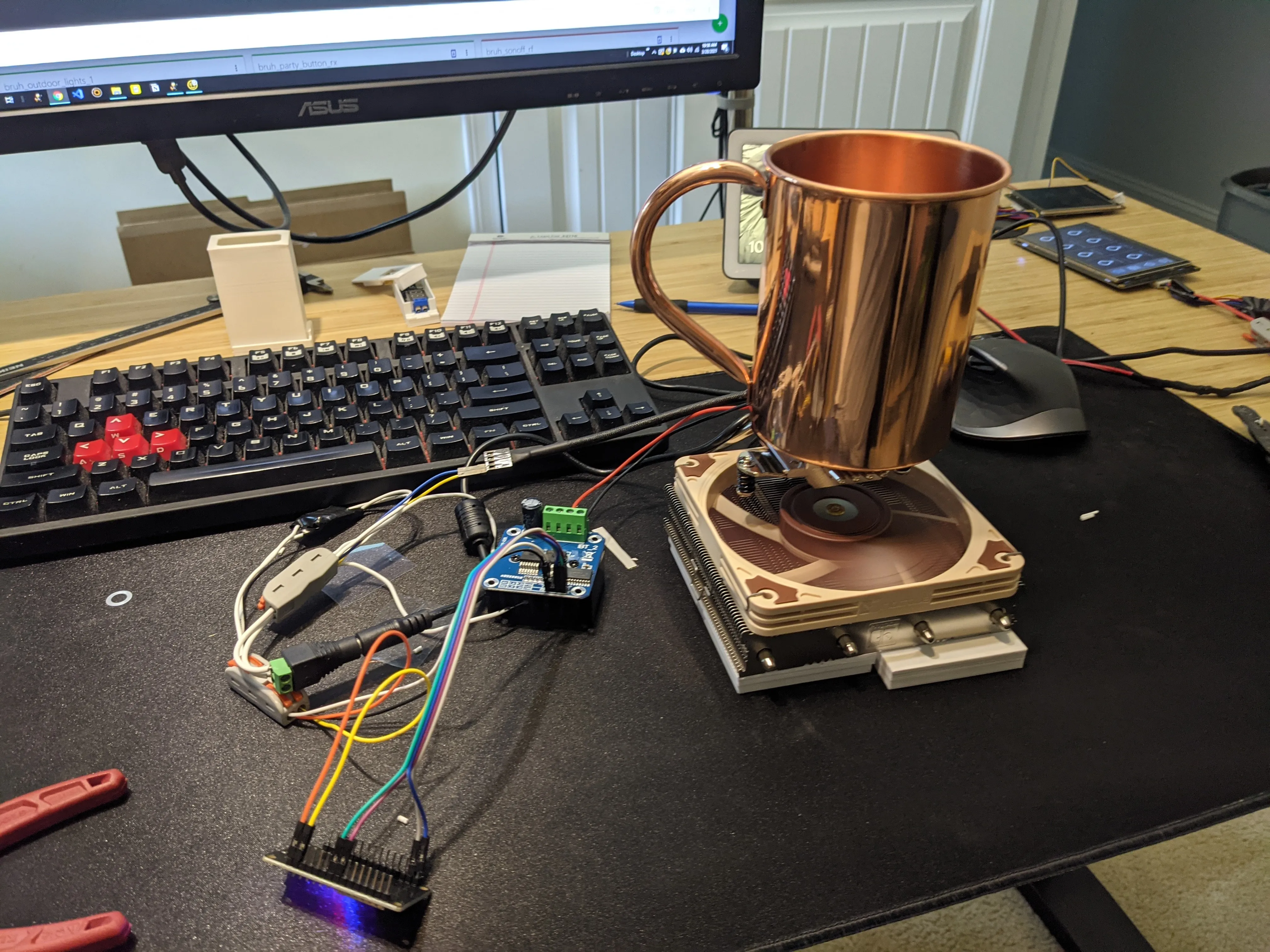
Every bottle warmer you can buy is a hot plate with a timer. Set it for four minutes, come back, and hope. This one is a Peltier module clamped under a copper mug with a thermocouple on the plate, so it warms to a temperature and then sits there — and because a Peltier is a heat pump rather than a heater, running the current the other way chills the bottle instead.
That last part is the whole reason the driver is an H-bridge and not a MOSFET.
How it works
A Peltier module does not make heat, it moves it. Put current through the 40 × 40 mm wafer and one ceramic face gets hot while the other gets cold. The face touching the mug is the hot one; the cold one has to be bolted to something that can feed it, and that something is a CPU cooler.
The cooler is not optional and it is not a place to economise. A Peltier’s ability to pump heat falls off as the difference between its two faces grows, and at its maximum ΔT it pumps nothing at all — it just sits there dissipating its own electrical losses. Starve the cold side and the module stalls. Give it a 120 mm tower of fins and a quiet fan and the cold face stays near room temperature, the module keeps pumping, and everything it pumps plus everything you put in electrically ends up in the bottle.
Using a CPU cooler buys you the second thing too: its mounting hardware. A Peltier is a thin ceramic sandwich that needs firm, even pressure across its whole face and cracks if you crank down one corner. A cooler’s spring-loaded mounting screws are a calibrated clamp that already solves that, with a backplate you can replace with a printed plate.
Parts
Some links below are Amazon affiliate links. As an Amazon Associate I earn from qualifying purchases — at no extra cost to you. It helps keep these guides free. Outside the US, they should send you to your own Amazon store; if one doesn't, searching the part number there will find it.
- TEC1-12712 Peltier modules, 5-pack — 40 × 40 mm, 12 V, 12 A. They come in fives because you will crack one, and because there is no such thing as one Peltier project.
- Noctua NH-L12S low-profile CPU cooler — the 120 mm PWM fan is in the box, so this one line covers the heat exchanger, the fan and the clamping hardware. It is the most expensive thing on the list and the one worth buying properly.
- 22 oz unlined copper Moscow-mule mug — a straight-sided copper sleeve the bottle stands in. Copper because it is the cheapest way to buy a large, tall, thermally excellent vessel; a stainless tumbler of the same shape conducts a fraction as well.
- BTS7960 43 A H-bridge module — a MOSFET board would run the Peltier one way for half the price. This runs it both ways, which is the difference between a bottle warmer and a bottle warmer-and-chiller.
- MAX6675 amplifier with K-type thermocouple — the probe is a ring lug on an M6 screw, so it bolts flat to the plate instead of being taped to it. That is why this and not a DS18B20.
- ESP32 dev board, 38-pin — you need two hardware PWM channels for the bridge and a third for the fan, plus SPI for the thermocouple. An ESP8266 will do it with software PWM; the ESP32 does it without thinking about it.
- 12 V 4 A supply — 48 W, which caps the module at about a third of its rating. That is a sensible place to run a warmer. If you want the full 12 A on tap, the 12 V 30 A enclosed supply is the honest answer and it needs a proper enclosure around it.
- MP1495 buck module, 5-pack — 12 V down to 5 V for the ESP32 and the logic side of the bridge. One supply in, one supply in the box.
- Thermal conductive glue for bonding the Peltier to the plate that carries the mug, or double-sided thermal tape if you want to take it apart again. The clamped face wants silicone thermal pad or ordinary paste — glue on both faces and the module is scrap the first time you change your mind.
- 18 AWG two-conductor silicone wire for the Peltier leads. It draws several amps continuously; 22 AWG hookup wire is not enough and gets warm enough to notice.
- DC barrel jacks and pigtails, 5.5 × 2.1 mm, lever-nut connectors and Dupont jumpers — the prototype in the photo is wired on these, which is why it is a prototype and also why it went together in an afternoon.
- PETG filament for the base. See the caution below before you reach for PLA+.
- M3 screw assortment and M3 heat-set inserts for the printed parts.
Run the module at 12 V. A TEC1-12712 is a 12 V part and the BTS7960 will happily accept a 24 V supply, which is a tempting way to get more power out of a brick you already own. PWM does not fix it: chopping 24 V still puts 24 V across the junctions on every pulse, and the thermal cycling that comes with it is what kills Peltiers early. If you want more heat, buy the bigger 12 V supply.
Wiring
The prototype has no sketch or ESPHome config in this folder, so there are no GPIO numbers on this page — pick your own and write them into your firmware. What is fixed is which module pin does what, and that part is worth having in one place.
| From | To | Notes |
|---|---|---|
| 12 V supply + | BTS7960 B+ | Screw terminal, 18 AWG |
| 12 V supply − | BTS7960 B− | |
| BTS7960 M+ / M− | Peltier red / black | Swap these and heat becomes cool |
| ESP32 PWM out | BTS7960 RPWM | One direction |
| ESP32 PWM out | BTS7960 LPWM | The other direction |
| 3.3 V | BTS7960 R_EN, L_EN, VCC | Enables tied high; logic rail, not motor rail |
| GND | BTS7960 GND | Common with the ESP32 |
| MAX6675 SO / CS / SCK | Three ESP32 GPIOs | SPI, read-only — the module has no MOSI |
| MAX6675 VCC / GND | 3.3 V / GND | |
| Noctua fan | 12 V, GND, PWM, tach | 4-pin; the tach line is optional |
Never drive RPWM and LPWM high at the same time. On a 43 A bridge that is a short across the supply through both half-bridges, and the module has the current capability to make it memorable.
The fan can be left running flat out on 12 V and ignored — it is a Noctua, it is inaudible, and a bottle warmer that runs for four minutes has no thermal reason to modulate it. Wire the PWM line anyway if you want the option later.
Assembly
-
Find the hot face. Wire the module to the bench supply for ten seconds and put a finger on each side. Do not trust the printed marking or a diagram on the internet; mark the hot face yourself with a Sharpie and move on.
-
Bond the hot face to the mug plate. Thermal glue here, because this joint has no clamp holding it — the plate, the module and the glue become one part.
-
Clamp the cold face to the cooler. Paste or a thermal pad on this side, and let the cooler’s own spring screws provide the pressure. Tighten the screws in diagonal pairs, a turn at a time, until the springs are compressed and no further. Ceramic does not warn you before it cracks.
-
Print a plate to stand in for the motherboard. The cooler’s backplate assumes there is a PCB between it and the mounting bars; a flat printed plate with the right hole pattern does the same job. That is what the white part in the photo is.
-
Fill the gap around the module. The wafer is only a few millimetres thick, so once it is clamped there is a 40 mm square window of air between two plates at very different temperatures. Anything closed-cell packed into that gap raises efficiency and cuts the condensation. Do not let it press on the ceramic hard enough to take load off the clamp.
-
Wire it, and test with water before milk. A mug of water and a kitchen thermometer tells you what the plate reading actually corresponds to.
Calibration
The thermocouple reads the plate, not the milk, and the plate always runs hotter than what is in the bottle — by more at the start of a cycle than at the end. Put a thermometer in a bottle of water, run the warmer, and log both numbers until you know the offset at the temperature you care about. Then set the target from the bottle’s number, not the plate’s.
The MAX6675 goes to 1024 °C, which is absurd for this and is not the problem it looks like: it resolves 0.25 °C and it is reading a probe bolted to metal, which is a far more stable measurement than a sensor dangling in air.
Milk goes in the bottle, the bottle goes in the mug. The mug is unlined copper — it is a heat-transfer sleeve, not a vessel. Nothing anybody drinks should touch it.
And set your ceiling in firmware, not in your head. Body temperature is the target, and nothing in this stack has an upper limit of its own — the module will keep pumping heat into the plate for as long as you give it current. That needs a hard limit in code and a cut-out you have actually tested, by unplugging the thermocouple mid-run and watching what the code does when the reading goes away.
Two traps
The cold side sweats. In warming mode the fin stack sits at or below room temperature while it feeds the module, and on a humid day it will collect water and drip. Everything electrical belongs beside the cooler, not under it, and the base wants to be a tray rather than a flat plate.
PLA is the wrong material here. PLA starts going soft around 60 °C, and the hot side of a loaded Peltier goes past that without trying. The printed parts are what hold the clamp, so the failure is not a part visibly sagging — it is the clamp relaxing, contact going, and the warmer quietly getting worse. PETG or ABS. The white parts in the photo are PLA+, which is fine on a bench and not fine in a finished unit.
What isn’t here yet
This page documents a working bench prototype, not a finished build. The printed base has no STL in the repo, and there is no sketch or ESPHome config — which is why there are no pin numbers above and why the project is still flagged as pending. Everything in the parts list is real and everything in the wiring table is fixed by the modules themselves, so the electronics are buildable today; the mechanical half is a photo and a description.
Files & downloads
The source files for this project aren't in the repo yet — there's nothing to download beyond the notes. They land in projects/peltier-bottle-warmer/ when they do, and this section fills itself in.